Understanding Positive Displacement: The Core Principle
Rotary gear pumps operate on a fundamental principle known as positive displacement. Unlike centrifugal pumps that accelerate fluid through impeller rotation, gear pumps mechanically trap and move fixed volumes of fluid with each pump revolution. This distinction is critical to understanding why gear pumps deliver precise, predictable flow rates independent of system pressure, viscosity, or downstream resistance.
In a rotary gear pump, two intermeshing external gears (one driven by motor, one idler) rotate in a close-fitting housing. The meshing action creates expanding and contracting cavities that trap fluid at the inlet and force it toward the discharge. This mechanical action ensures consistent forward motion of all pumped fluid—no fluid slips backward through impeller clearances, and no re-circulation occurs. Flow depends solely on gear displacement and rotation speed, not on pressure or fluid properties.
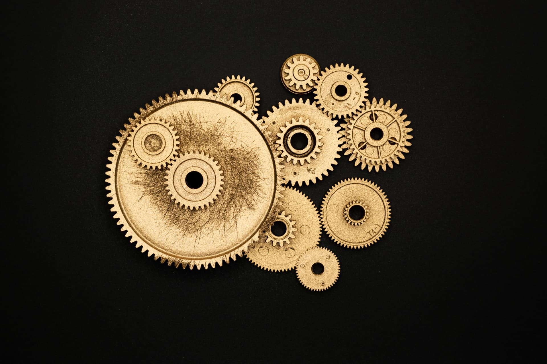
Industrial gear mechanism - the foundation of rotary pump operation
Gear Pump Geometry: External vs. Internal Designs
Gear pumps come in two primary configurations: external gear and internal gear. NAPCO pumps are external gear designs, which offer distinct advantages for industrial fluid transfer.
External Gear Pump Design
In an external gear pump, two gears mesh outside each other. One gear (the driver) is coupled to the motor shaft. The second gear (the idler) floats on its own shaft, driven by the meshing first gear. Both gears rotate in the same direction relative to their own shafts but rotate in opposite directions relative to the pump center. The housing forms a close envelope around both gears, with the inlet port at the meshing point where cavities expand, and the discharge port at the point where cavities contract.
External gear advantages: Simple robust design with only two rotating parts; field-serviceable with standard repair kits; excellent for self-priming and viscous fluids; capable of reversible operation; handles gas-entrained inlet streams.
Internal Gear Pump Design
Internal gear pumps feature a smaller external gear meshing with the inside of a larger internal (ring) gear. The internal gear is stationary while the outer gear orbits. This orbital action creates expanding cavities at the inlet and contracting cavities at the discharge. Internal gear pumps produce smoother flow with less pulsation than external designs.
Internal gear pumps are not used by NAPCO; they are more complex, harder to service, and less suitable for highly viscous fluids. External gear design is the industrial standard for chemical transfer, adhesive pumping, and high-viscosity applications.
The Meshing Cycle: Four Stages of Flow
A complete pump cycle occurs every time the gears advance one tooth engagement. Understanding the four stages of the meshing cycle clarifies how gear pumps achieve positive displacement.
Stage 1: Cavity Expansion at Inlet
As gears rotate, the meshing point moves around the pump center. At the inlet port location, gears are moving away from each other, expanding the cavity between a tooth on one gear and a tooth space on the other. Atmospheric pressure (or system suction pressure) pushes fluid into this expanding cavity from the inlet port. Fluid continues flowing into the cavity as the meshing area sweeps around the pump.
Stage 2: Fluid Sealing Between Gears
Once the meshing point moves past the inlet port, the cavity is sealed between the two gears. Fluid trapped in this cavity is now isolated from both inlet and discharge. The volume of trapped fluid remains approximately constant as gears continue rotating. This sealing action is critical—if gaps between gears are too loose, fluid slips back through instead of being transported forward.
Stage 3: Cavity Compression and Pressure Rise
As gears continue rotating, the meshing point approaches the discharge port. The cavity between gears narrows as one gear tooth advances into the space left by the other gear. This compression action mechanically reduces the volume available for trapped fluid. Pressure inside the cavity rises as the fluid is squeezed into an ever-smaller space. This pressure rise is not caused by system resistance; it is a direct result of the mechanical compression ratio of the gear design.
Stage 4: Cavity Discharge
When the compressing cavity reaches the discharge port, high-pressure fluid is forced out of the pump. The pump outlet pressure equals the pressure in the compressing cavity. System back-pressure (load pressure, filter pressure, valve cracking pressure) must be overcome for discharge to occur. Once discharge begins, fluid flows out at a rate determined by the gear meshing action and pump speed.
Key insight: Gear pump discharge pressure is load-driven rather than self-generated. The pump compresses trapped fluid and pushes it forward; if system resistance is low, discharge pressure remains low. If system back-pressure is high (closed valve, filled tank, high-viscosity fluid), the pump must push harder against the load, and discharge pressure rises to match the resistance (up to the pump's rated maximum).
Pump Displacement: The Foundation of Flow Calculation
Pump displacement is the volume of fluid moved per complete revolution. Displacement is expressed in cubic centimeters per revolution (cc/rev) or cubic inches per revolution (ci/rev). Displacement depends entirely on gear geometry: pitch diameter, gear face width (tooth length), and number of teeth.
Displacement Geometry
Larger gears have larger pitch diameters, creating larger cavities between meshing teeth. Wider gear faces (longer tooth flanks) provide more tooth depth, trapping larger volumes. More gear teeth result in smoother operation and smaller per-tooth displacement but achieve the same total displacement over a full revolution. NAPCO's PA300 series (approximately 2,140 cc/rev) uses larger gears than the PA200 series (approximately 1,375 cc/rev), resulting in over 50% more displacement per revolution.
Flow Rate Calculation Formula
Theoretical flow rate is calculated using a simple linear formula:
GPM = (Displacement cc/rev × RPM) ÷ 3,785
(3,785 is the number of cubic centimeters in one US gallon.) For example, a PA300 (≈2,140 cc/rev) running at 280 RPM calculates to:
GPM = (2,140 × 280) ÷ 3,785 ≈ 158 GPM
Critical insight: Flow is directly proportional to pump speed. Doubling RPM doubles flow output. Halving RPM halves flow. This linear relationship is why gear pumps enable precise metering via speed control—unlike centrifugal pumps where flow varies with the cube of speed.
Pressure Generation: Load-Driven vs. Self-Generated
A common misconception is that gear pumps generate pressure. In reality, gear pumps generate flow, and system resistance creates pressure.
How Pressure Develops in Gear Pumps
Pressure in a gear pump discharge equals the resistance the pump must overcome:
- No load (zero back-pressure): Discharge pressure ≈ 0 PSI (atmospheric plus friction losses).
- Moderate load (open valve, low restriction): Discharge pressure ≈ 10–50 PSI.
- High resistance (closed valve, high-viscosity fluid, tight filter): Discharge pressure approaches pump maximum (100 PSI for NAPCO models).
The pump physically compresses trapped fluid and pushes it forward. As the system resists flow (through valves, piping friction, or fluid viscosity), the pump pressure must rise to overcome that resistance. If a discharge valve is closed completely, pump pressure rises to the relief valve setting or pump mechanical limit—whichever comes first.
Pump Power and Pressure Relationship
Motor power consumption increases with pressure. At zero back-pressure, the pump consumes minimal power (friction losses only). At maximum pressure, the pump consumes maximum power. The relationship is:
Horsepower = (GPM × PSI) ÷ 1,714
A PA300 delivering 140 GPM at 100 PSI requires approximately 13.4 HP. Running the same pump at 10 PSI requires only <1 HP. This is why oversizing the system relief valve or operating at lower pressures significantly reduces energy consumption.
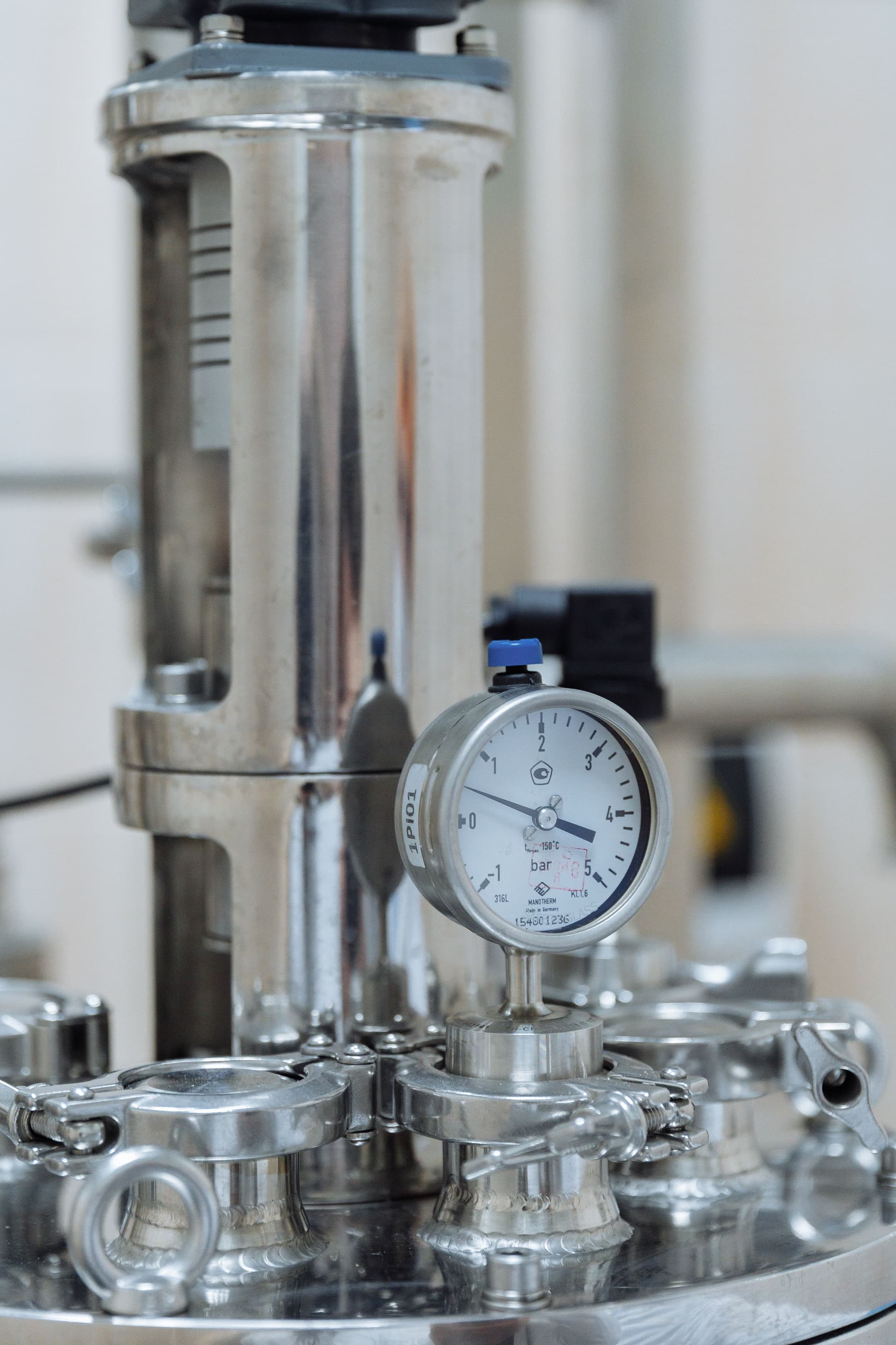
Precision manufacturing - critical for achieving tight gear clearances
Volumetric Efficiency and Internal Slippage
Theoretical displacement assumes perfect sealing between meshing gears and between gears and the pump body. In reality, small clearances exist (typically 0.001–0.005 inches), allowing fluid to slip backward across gear flanks and from discharge back to inlet. Slippage reduces actual flow output below theoretical flow—the difference is called volumetric loss.
Volumetric Efficiency Definition
Volumetric efficiency is the ratio of actual flow delivered to theoretical displacement-based flow:
Volumetric Efficiency (%) = (Actual GPM ÷ Theoretical GPM) × 100
Efficiency vs. Pressure and Viscosity
At low pressure (<20 PSI): Volumetric efficiency is 95–98%. Tight clearances between gears seal fluid effectively. Slippage is minimal.
At moderate pressure (50–100 PSI): Efficiency drops to 90–95%. Higher pressure increases leakage across radial clearances and gear tooth flanks.
At high pressure (100 PSI, pump maximum): Efficiency falls to 85–90%. Increased pressure differential accelerates slippage. Actual PA300 delivers ~140 GPM instead of theoretical 158 GPM at 100 PSI.
Fluid viscosity dramatically improves efficiency: High-viscosity fluids (honey, adhesive, asphalt) are more resistant to slipping across clearances. A 100 cSt fluid may achieve 98% efficiency even at 100 PSI, while a thin 1 cSt fluid achieves only 85% efficiency at the same pressure. This is why gear pumps excel with viscous fluids—the fluid itself seals the clearances.
Mechanical Efficiency (Overall Pump Efficiency)
Mechanical (overall) efficiency accounts for friction losses in gear teeth, bearings, and seals. Typical gear pump mechanical efficiency ranges from 85–92%, depending on speed, viscosity, and design. A pump with 90% volumetric efficiency and 90% mechanical efficiency delivers 81% overall efficiency (0.90 × 0.90 = 0.81).
Self-Priming: Why Gear Pumps Handle Air
Self-priming is the ability to remove air from the inlet and discharge the pump, allowing operation from a dry state or partially evacuated inlet. Gear pumps are excellent self-primers; centrifugal pumps cannot prime at all.
How Self-Priming Works
When the pump starts with air in the inlet, the expanding cavities at the inlet port create a vacuum. This vacuum pulls air through the inlet line, filling the expanding cavities. As gears continue rotating, the cavities close off, trapping and compressing the air. The compressed air is then forced toward the discharge port and expelled. This cycle repeats: pull air in, trap it, compress it, push it out.
Eventually, when all air is removed and the discharge line fills with fluid, the pump transitions to normal fluid pumping. The expansion-compression cycle that removed air now removes liquid and moves it toward the discharge.
Why Centrifugal Pumps Cannot Self-Prime
Centrifugal pump impellers accelerate fluid by throwing it outward. Air bubbles are lighter and resist acceleration, breaking away from the impeller blade tips. Instead of being forced toward discharge, air bubbles recirculate back to the eye of the impeller, creating an air lock. Centrifugal pumps require pre-filling (priming) before starting—they cannot prime themselves from dry inlet conditions.
Practical Self-Priming Limits
While gear pumps self-prime, inlet lift capability is limited by atmospheric pressure. Standard atmosphere can support a water column approximately 34 feet high (10.3 meters). Most gear pumps tolerate 6–8 feet of inlet lift (suction lift) before vapor cavitation occurs. Operating conditions, fluid vapor pressure, and pump speed affect actual inlet lift limits.
Bi-Directional Operation: Reversible Flow Control
External gear pumps can operate in both forward and reverse directions without modification. Reversing the inlet and discharge port connections reverses the pump's flow direction—the pump physically moves fluid in the opposite direction without requiring motor reversal or check valves.
How Reversibility Works
Consider a pump with inlet on the left and discharge on the right. If motor rotation remains constant but the fluid connections are swapped (discharge hose moved to left port, inlet moved to right port), the pump flow reverses. The same meshing action that moved fluid left-to-right now moves fluid right-to-left. The pump's mechanical direction is unchanged, but fluid flow direction is reversed.
Applications of Bi-Directional Operation
- Dual-direction transfer: Load fluid from tank A to tank B, or reverse to load tank B to tank A, using a single pump and switchable hose connections.
- Flush and fill: Forward mode fills a system; reverse mode drains and flushes it through the same pump.
- Return line integration: Pump discharge can feed a return line while return fluid pumps back through the inlet, reducing the need for separate circulation pumps.
Reversibility is one reason NAPCO gear pumps are widely used in flexible industrial systems—one pump design handles multiple operational scenarios without additional equipment.
NAPCO Rotary Gear Pump Design: External Gear Architecture
NAPCO manufactures external gear pumps exclusively. The design philosophy prioritizes simplicity, durability, field serviceability, and performance across a wide range of industrial fluids. All NAPCO pumps use the same fundamental operating principle but differ in displacement and construction materials.
Two Primary Product Lines
PA Series (Pumps): Standard production pumps for general industrial fluid transfer. Available in ductile iron (C-suffix) or stainless steel (S-suffix for corrosive chemical service). PA300 (3-inch, 158 GPM at 280 RPM) and PA200 (2-inch, 69 GPM at 190 RPM) are the two displacement sizes.
PK Series (Rebuild Kits): Field-replaceable component sets enabling on-site pump rebuild without factory return. Kits include drive and idler gear assemblies (gears pre-mounted on their shafts), roller bearings, high- and low-pressure seals, and center case gaskets. The availability of kits reflects NAPCO's commitment to minimizing customer downtime.
Stainless Steel Option: The PA-S Advantage
NAPCO's stainless steel pumps (PA300S, PA200S) use stainless steel housings with high- and low-pressure Viton seals — see the material selection guide. Stainless construction resists corrosion from ammonium nitrate emulsions, acids, and food-grade fluids, extending service life in demanding applications. Both seal sets are included in every repair kit, so seal replacement is part of a routine field rebuild.
Material Options for Different Applications
Ductile Iron Construction: Standard for petroleum, food, adhesive, and general industrial applications. Cost-effective and durable for non-aggressive fluids.
Stainless Steel Construction: Required for chemical processing, corrosive liquid transfer, and food-grade applications where material contamination or environmental compliance is critical.
Related Technical Resources
- What Is a Rotary Gear Pump? Complete Overview
- How to Size a Rotary Gear Pump
- Choosing the Right Positive Displacement Pump: Gear vs. Vane vs. Piston
- Gear Pumps vs. Progressive Cavity Pumps: When to Choose Each
- Engineering Specifications & Performance Data
- NAPCO Rotary Gear Pump Models & Specifications
- Stainless Steel vs. Ductile Iron Pump Bodies
Need Technical Clarification on Gear Pump Operation?
NAPCO's engineering team is available to discuss pump displacement, efficiency curves, pressure-flow relationships, or any aspect of rotary gear pump operation. Contact us with your application details and specific questions.
Contact NAPCO Engineering