NAPCO rotary gear pumps have been designed and equipped to provide satisfactory use. They come with especially hardened surfaces on the shafts where the seals and bearings ride to extend the operating life of those pump parts. The pump chamber, shafts, and gears have been molded and machined to exacting dimensional tolerances, and the seals and bearings selected to provide greater operating efficiency and extended wear. Despite these features, the pump will still require proper maintenance and operation for safe, satisfactory performance.
Lubrication
NAPCO rotary gear pumps are designed with eight (8) easily accessible grease zerk fittings. Four of these zerk fittings allow grease to flow between the lip seals and high pressure seals on each shaft (two seal grease cavities on each shaft). Four other zerk fittings lubricate the bearings. The pump comes fully lubricated with NGLI #2 grease and ready for use.
ONCE THE PUMP IS IN OPERATION IT IS ABSOLUTELY CRITICAL THAT A REGULAR LUBRICATION PROGRAM BE FOLLOWED BY THE USER TO ALLOW THE PUMP TO OPERATE AS DESIGNED AND PREVENT PREMATURE FAILURE OF THE MOVING PARTS.
Gaskets
NAPCO Rotary Gear Pumps come installed with one .016 chamber gasket on the drive side bearing housing/side cover and three .008 inch chamber gaskets on the non-drive side bearing housing/side cover. Efficiency can be improved where operational wear has occurred by removing one of the three .008 inch non-drive side gaskets to tighten clearances and restore operational efficiency.
UNLESS ESPECIALLY MODIFIED, NAPCO PUMPS LEAVE THE FACTORY WITH APPROXIMATELY .008 INCH COMBINED CLEARANCE BETWEEN THE ENDS OF THE GEARS AND ADJACENT BEARING HOUSING SURFACES.
High temperature, or other unusual operating conditions, may dictate some variance in gear/housing clearances.
Seals
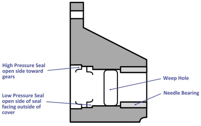
NAPCO utilizes a combination of high pressure and low pressure seals in its pumps. When re-installing or replacing these seals, it is very important that they be re-installed in the correct load-bearing direction to assure proper sealing of the pump chamber and elimination of excessive pressure buildup in the grease cavity. The diagram below shows the direction the open side of each seal should face in relation to the gears and pump chamber.
Drive Gear and Idler Gear Assemblies
NAPCO pump gears are pressure-fitted onto the shafts. Because most NAPCO customers lack the equipment to pull off and press a new gear on an existing pump shaft, NAPCO offers its customers drive gear and idler gear "assemblies" with the gear already mounted on the appropriate shaft. These assemblies are included in the NAPCO Spare Parts Kit, but the customer may also order them separately. Please identify the appropriate gear assembly and part number from the following list:
| 2″ Ductile Iron Pump (PA200C) | |
|---|---|
| Identification Number | Description |
| PA250C | 2″ ductile iron drive shaft with mounted nitrile gear |
| PA251C | 2″ ductile iron idler shaft with mounted nitrile gear |
| 2″ Stainless Steel Pump (PA200S) | |
|---|---|
| Identification Number | Description |
| PA250S | 2″ stainless steel drive shaft with mounted nitrile gear |
| PA251S | 2″ stainless steel idler shaft with mounted nitrile gear |
| 3″ Ductile Iron Pump (PA300C) | |
|---|---|
| Identification Number | Description |
| PA350C | 3″ ductile iron drive shaft with mounted nitrile gear |
| PA351C | 3″ ductile iron idler shaft with mounted nitrile gear |
| 3″ Stainless Steel Pump (PA300S) | |
|---|---|
| Identification Number | Description |
| PA350S | 3″ stainless steel drive shaft with mounted nitrile gear |
| PA351S | 3″ stainless steel idler shaft with mounted nitrile gear |
Factory-matched repair kits include complete gear assemblies, bearings, seals, and gaskets. Use our Pump Identification page to confirm your model and corresponding part numbers, or refer to the repair procedures for step-by-step rebuild instructions.
Repair Kit Installation Videos
Watch the complete repair kit installation procedure. These three-part videos demonstrate how to disassemble, inspect, install components, and reassemble a NAPCO rotary gear pump in the field.
Part 1: Disassembly & Inspection
Part 2: Component Installation
Part 3: Reassembly & Testing
Related Resources
- Gear Pump Cavitation Guide — Prevent cavitation damage through proper maintenance and system design.
- Field Maintenance for Rotary Gear Pumps — Preventive maintenance schedules and field service best practices.
- Pump Repair Kit vs. Replacement — Cost analysis: when to rebuild vs. replace your pump.
- Gear Pump Service Kit Finder — Match the correct factory gear pump service kit to your pump model and material.
- Repair & Replacement Parts — Disassembly, inspection, and reassembly procedures.
- Repair Kit Finder — Match the correct factory kit to your pump model.
- Engineering & Performance Data — Flow rates, pressure ratings, and material specifications.
Need Maintenance Support?
Contact NAPCO for maintenance guidance, replacement parts, or to order a factory-matched repair kit.
Contact NAPCO