Repair or Replacing Pump Parts
The NAPCO rotary gear pump will eventually lose operational efficiency as a result of wear of the moving parts. A bearing housing/side cover can be easily removed in order to observe the condition of the gears and inner pump chamber and determine whether any parts need replacement.
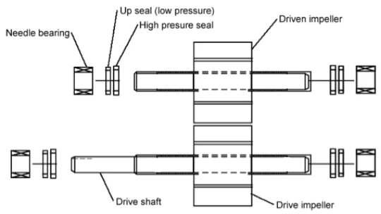
Whenever a bearing housing/side cover is removed and/or shafts and gears are replaced, it is extremely important, when pulling out or re-inserting the shafts, that care be taken that the shaft ends do not nick, damage, or dislodge the seals and bearings in the bearing housing/side covers. Any such damage or movement will cause the pump to leak and quickly fail. NAPCO has tapered the ends of the shafts to facilitate their removal and insertion through the seals and bearings. NAPCO also recommends that a lubricant be applied to the tapered end of the shaft to further facilitate moving it through the seals and bearings.
NAPCO Repair Kits
Individual pump spare or replacement parts can be ordered from NAPCO or its authorized distributors. NAPCO also offers “repair kits” that include all the moving or wear parts in a NAPCO pump typically needing replacement. A NAPCO Repair Kit contains:
- 1 drive gear assembly and one idler gear assembly
- 4 roller bearings
- 4 high pressure seals
- 4 low pressure seals
- 2 × .016 inch thick center case gaskets
- 3 × .008 inch thick center case gaskets
A NAPCO 2″ pump (PA200C ductile iron pump or PA200S stainless pump) will require a PK200C (for ductile pump) or PK200S (for stainless pump) repair kit. A NAPCO 3″ pump (PA300C ductile iron pump or PA300S stainless pump) will require a PK300C (for ductile pump) or PK300S (for stainless pump) repair kit. If a customer has ordered a ductile iron pump modified to contain stainless steel shafts, that pump will require a stainless steel pump Repair Kit. Use our Kit Finder to match the correct repair kit to your pump, or visit the Pump Identification page to confirm your model.
Repair & Installation Procedure
Periodic Inspection of Internal Working Parts
Periodically, or upon indication of loss of performance, the pump can be easily opened, inspected, and cleaned by following the steps below. Follow applicable steps to reassemble the pump properly.
- Quick internal inspection and pump cleanout:
- Close valves and lock out drive.
- The non-drive bearing housing/side cover may be removed to remove blockages and inspect for damage.
Inspection and/or Repair of Pump
Disassembly
- Remove non-drive bearing housing/side cover (two bolts with washer & O-rings). Note gasket locations for reassembly.
- Remove top idler gear and pull by hand.
- Remove drive gear, taking care not to damage seals.
- Remove drive side bearing housing/side cover and gaskets.
- Remove bearings, seals, and note orientation.
Clean and Inspection
- Clean all pump parts of product and old grease.
- Inspect all parts, particularly gear rubber for wear or damage, and bearings, seals, and gaskets for wear.
Reassembly
- Install 4 bearings. Secure with set screws and Loctite 222 on threads.
- Install 4 low pressure seals until seals seat on lower shoulder.
- Install 4 high pressure seals until flush with upper shoulder.
- Fit 1 × .016″ drive side gasket with grease. Orient to allow access to grease nipples.
- Fit drive side bearing housing/side cover, align pins, tighten 12 bolts evenly to 35 ft/lbs (48 Nm).
- Adhere 2 × .008″ gaskets to remaining bearing housing/side cover, align over pins, and secure evenly.
- Torque 4 equally spaced bolts to 35 ft/lbs (48 Nm). Adjust gear free play as needed by adding or removing gaskets.
- Grease all bearings and seals thoroughly (7 strokes each). Evidence of grease should be visible in the weep hole and bearing area.
- Rotate gears by hand — they should not bind. Ensure drive coupling has free play.
Prime and Test Pump
- Run the pump after prime. It may be necessary to use the relief valve.
- Check for abnormal noise or vibration; verify rotation direction.
- If vibration or binding occurs, verify gear alignment and gasket spacing.
Watch: How to Rebuild a NAPCO Pump
See the complete field rebuild procedure in action. This three-part video series shows disassembly, component installation, and reassembly of a NAPCO rotary gear pump using a factory repair kit.
Part 1: Disassembly & Inspection
Part 2: Component Installation
Part 3: Reassembly & Testing
Related Resources
- Pump Repair Kit vs. Replacement — Cost-benefit analysis of rebuilding your pump versus replacement.
- Gear Pump Cavitation Guide — Understand cavitation damage, prevention, and repair implications.
- Field Maintenance for Rotary Gear Pumps — Preventive maintenance schedules and field service procedures.
- Maintenance Procedures — Lubrication, gasket, and seal orientation guidance.
- Gear Pump Service Kit Finder — Match the correct factory gear pump service kit to your pump model.
- Warranty Information — Coverage details and service requirements.
Need Repair Parts or Technical Assistance?
Contact NAPCO directly for repair kits, replacement parts, or guidance on rebuilding your rotary gear pump.
Contact NAPCO